

This is an old revision of the document!
Unit 6: Analog I/O and Process Control
Unit 6 Labs
Download This Document
1. Introduction
The purpose of this laboratory exercise is to investigate applications of embedded controllers to real time control algorithms that employ analog inputs and analog outputs. You will use a computer algorithm to implement a closed-loop processor fro motor speed control. You will see how feedback can be used to linearize an inherently nonlinear process and result in zero steady state control error.
2. Objectives
- Generate PWM outputs to implement variable motor supply voltage.
- Implement a tachometer operation using PIC32 Timers.
- Develop MPLAB X projects that implement open-loop and closed-loop motor control.
- Develop the C program code to implement a PI controller and a moving average digital filter.
- Manage multiple background tasks in an interrupt driven system.
- To monitor and display data from a process running in real-time.
3. Basic Knowledge
- Suggested reading: Embedded Computing and Mechatronics with the PIC32 Microcontroller
- Basic circuit theory
- Fundamentals of programming with C
- How to configure I/O pins on a Microchip® PIC32 PPS microprocessor
- How to implement a real-time system using preemptive foreground – background task control
- How to generate a PWM output with the PIC32 processor
- How to configure the Analog Discovery to display logic traces
- How to implement the design process for embedded processor based systems
4. Equipment List
4.1. Hardware
- Workstation computer running Windows 10 or higher, MAC OS, or Linux
In addition, we suggest the following instruments:
4.2. Software
The following programs must be installed on your development workstation:
- WaveForms 2015 (if using the Analog Discovery 2)
- Spreadsheet application (such as Microsoft Excel)
5. Project Takeaways
- How to read analog voltage with a PIC32 processor.
- How to use the PIC32 Output Compare to implement a PWM analog output.
- How to use the PIC32 Input Capture period measurement to implement a tachometer.
- The advantages of using period measurements as opposed to frequency measurements and vice versa.
- Fundamental digital filtering concepts for data smoothing.
- Open-loop and closed-loop process control.
6. Fundamental Concepts
This unit introduces the concepts of process control of electro-mechanical systems that employ analog and digital I/O. Reference 1 is the suggested companion reference and certain sections will be noted throughout this unit as well as labs 6a and 6b. Be advised that this reference is based on the PIC32MX750 processor and not the PIC32MX370 processor used on the Basys MX3 trainer board. This reference also uses a different hardware platform for the software examples. The significant differences between these two processors are discussed in Appendix C of this suggested reference book.
6.1. Process Control
Automated process control is an engineering discipline that deals with architectures, mechanisms and algorithms for maintaining the output of a specific process within a desired range. In general, automation is the control of equipment and systems that require minimum human interaction. Figure 6.1 is a block diagram representing the main elements in microprocessor based automated system that could be used to implement an automobile speed control. Although there are various forms of control theory, Reference 2 describes two forms of control: open-loop and closed-loop.
The block diagram of Fig. 6.1 has partitioned the automated process into elements of hardware and software that will be described in detail below. The elements shown inside the shaded blue box are implemented using software within the microprocessor. The elements shown inside the shaded green boxes are parts needed for open loop control processing. The elements shown inside the shaded orange boxes are parts that are not required for open loop but provide instrumentation to monitor the performance of the open loop system. The shaded yellow box element is added to the open loop control and instrumentation elements to form a completed closed loop system. The input signals that are continuous in nature must be converted from analog to digital by using an analog-to-digital converter (ADC). Output signals that are used to control mechanical and thermal devices such as motors, heaters, and air conditioners require the digital variable to be converted to an analog signal using a digital-to-analog converter (DAC). Both the ADC and DAC will be discussed in detail to follow.
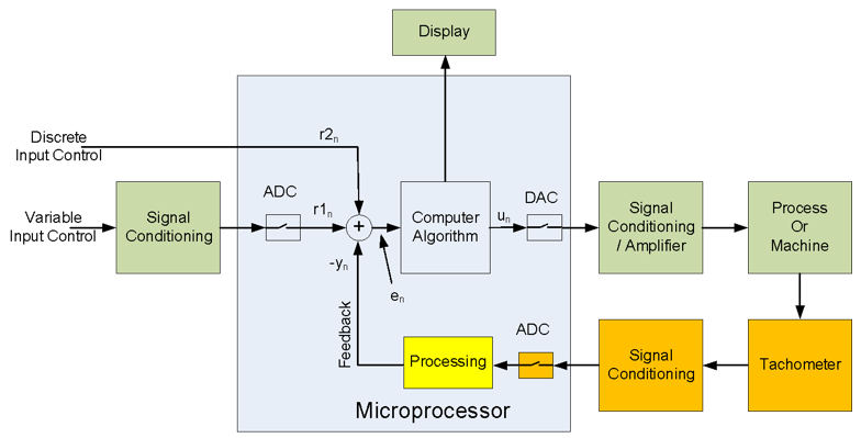 Figure 6.1. Automated process control block diagram.
6.1.1. Open-loop Control
Open-loop control of a system results when there is no feedback from the system output back into the control algorithm. In other words, an open-loop controller does not determine if the processor is generating the desired output, given the system inputs, because the system does not observe the output of the processes that it is controlling. Consequently, a true open-loop system cannot correct any errors or compensate for disturbances to the system.1) The signal path from input to output is called feed forward, as the output is some closed form function of the input signal or signals. For example, using the open loop automobile speed control, the gas flow to the engine is controlled by the position of the accelerator but the vehicle ground speed is not necessarily directly related to the accelerator position. The driver must manually adjust the gas flow so the vehicle travels at the desired speed. If the inclination of the road changes up or down, the driver must make adjustments in the accelerator position to maintain a constant speed, in part by watching the speedometer.
6.1.2. Closed-loop Control
1)
Open-loop controller, https://en.wikipedia.org/wiki/Open-loop_controller