Table of Contents
Solderless Breadboards
The solderless breadboard (generally a large, white, plastic component with rows and columns of holes) provides a working space where temporary circuits can easily be built1. Leads of electrical components (e.g. resistors) can easily be pushed into the breadboard holes.
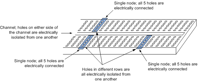
A typical breadboard has a large number of holes which are organized in rows of five or six. The holes in any single row are electrically connected to one another. Any two rows of holes are isolated electrically from one another. A central groove or channel generally separates two banks of these holes. The overall situation is illustrated in Fig. 1. The holes on either side of this channel are also not electrically connected. The channel is not important to us now, but will become useful in later lab assignments when we create circuits containing integrated circuit (IC) chips packaged as DIPS (Dual In-Line Packages).
Definitions
- Holes in a breadboard which are electrically connected are said to be at the same node in a circuit. A node is a point in a circuit where two or more components are interconnected by a short circuit. No energy is required to transfer current through a short circuit, so the short circuit does not restrict the flow of current—it has zero resistance. This means that there can be (theoretically) no voltage difference between two holes in any single row in a breadboard.
- No current will flow from one hole to another on a breadboard if the holes are not electrically connected. Different physical points in a circuit which are not electrically connected are sometimes said to be connected by an open circuit. No current can flow through an open circuit. There is no limit to the possible voltage difference across an open circuit.
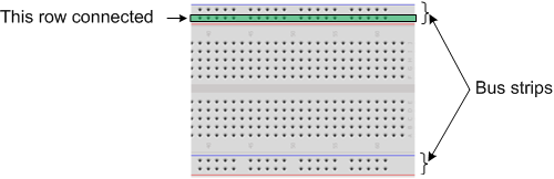
Some breadboards have, in addition to the hole layout shown in Fig. 1, supplementary rows of holes running the entire length of the breadboard. These rows are called bus strips, and are indicated in Fig. 2. Bus strips are mostly useful when connecting the same voltage level at multiple locations in larger-scale circuits. Ground and fixed voltage supplies, for example, may be used in multiple stages in an overall circuit. Bus strips are often marked with a red or blue line running next to them.
A number of additional variants on this basic setup are relatively common. For example, larger breadboards may contain multiple breadboards like those shown in Fig. 2 placed side-by-side. Other breadboards may have terminal strips which provide banana-plug type connectors on the breadboard; these types of connectors can facilitate connection of certain types of equipment to the breadboard. None of the variations, however, affect the basic breadboard functionality shown in Fig. 1.
Important Points
- Most breadboards have holes which are organized in rows of five.
- The holes in each row are connected electrically. That is, if you insert terminals of electrical components in two holes in the same row, you have “connected” those two terminals to one another.
- The holes in different rows are isolated electrically. That is, if you insert terminals of electrical components in two holes which are in different rows, those terminals are not connected to one another.
- Breadboards will generally have one or more channels or grooves in them. The channels are for inserting integrated circuits (ICs) in the breadboard. The ICs are inserted such that they straddle the channel. Holes on either side of the channel are isolated from one another.
Test Your Knowledge
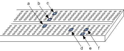
Several holes are indicated on the breadboard images below. Indicate whether the following pairs of holes are connected or not.
I. a and b
II. b and c
III. a and c
IV. a and d
V. e and f
VI. d and f
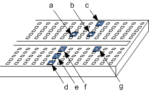
Answers
- Image one:
- I. Not connected.
- II. Connected
- III. Not connected.
- IV. Not connected.
- V. Connected.
- VI. Not connected.
- Holes d, e, and f are connected to one another. Holes b and c are also connected to one another. No other highlighted holes are connected to one another.