Table of Contents
Lumped Parameter Circuits and Nodes
Introduction
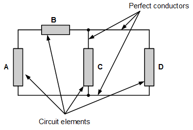
We will consider that our electrical circuits consist of two or more circuit elements interconnected by perfect conductors. The circuit elements can be resistors, transistors, capacitors, inductors, integrated circuits, or any other device which has an effect on voltage or current. Our “perfect” conductors can be wires that allow current to flow from one element to another. This representation of electrical circuits contains an underlying assumption: only the circuit elements have an effect on the energy storage or transfer in the circuit1). Since the energy is lumped at discrete points in the circuit (in the components), a circuit which is represented this way is called a lumped-parameter circuit2).
Figure 1 shows an example of a lumped parameters circuit. The circuit elements A, B, C, and D affect the energy in the circuit; the connecting lines between them are perfect conductors —they can transfer any amount of current without storing or dissipating energy.
Circuit Nodes
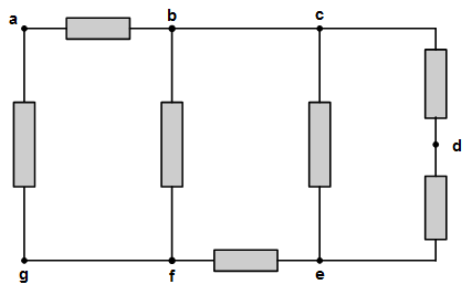
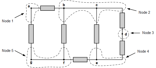
Circuit elements in lumped parameters circuits are connected at nodes. Identification of circuit nodes will be extremely important to us when we are creating and analyzing circuits. Every node has a single unique voltage, so there can be no voltage drops (and thus no circuit elements) within a node. Perfect conductors do not cause voltage drops, so a node can contain perfect conductors. An example circuit is shown in Fig. 2(a). A common error would be to identify seven nodes in the circuit, as indicated by points a, b, c, d, e, f, and g. However, nodes b and c are connected only by a perfect conductor, so there is no voltage difference between those two points; they are part of the same node. Likewise, a perfect conductor connects points f and g. Therefore, there are only five nodes in the circuit, as shown in Fig. 2(b).
Definitions:
- A node is an electrical “point” where two or more circuit elements are connected. Since perfect conductors don't necessarily count as circuit elements, nodes can contain perfect conductors.
- Circuit nodes can also be identified by the fact that they are portions of a circuit which are all at the same voltage. Since there is no voltage drop across a perfect conductor, any points in a circuit which are connected by perfect conductors will be at the same voltage, and will thus be part of the same node.
Physical Circuit Nodes
Solderless Breadboards
Physically, circuit elements can be interconnected in a number of ways. We will be creating our circuits on solderless breadboards, however, so we only have a couple of options:
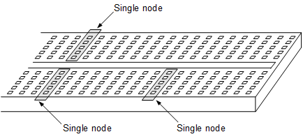
- On a solderless breadboard, all of the holes in a single row are connected by a conductor. Thus, all five of these holes automatically form a single node, as shown in Fig. 3. This allows us to interconnect components by inserting their terminals in holes in the same row.
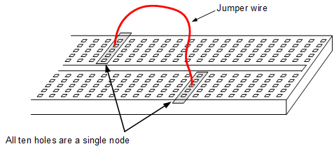
- We can also make connections with jumper wires. The jumper wires are good conductors, so we will assume that points connected with jumper wires become a single node. Figure 4 shows how this approach can be used to create nodes with more than five holes on a breadboard.
Obviously, identifying any physical connector (such as a wire) as a “perfect” conductor will be incorrect; any wire will have some non-zero resistance, and will cause an amount of voltage difference between its ends. The trick is that the resistance of the conductor should be negligible compared to the resistance of the other components in the circuit in order for it to be considered “close enough” to zero to make no difference. For example, a wire with a resistance of 0.1Ω can probably be neglected if it connects two 10kΩ resistors.
Important Points
- Lumped-parameters circuits consist of discrete circuit components connected by, what are assumed to be, perfect conductors. An underlying assumption of lumped parameters circuits is that the perfect conductors instantaneously transfer current with no voltage drop.
- The lumped-parameters circuit model is inappropriate if the distances involved are large or the voltages and currents are changing very rapidly. In these cases, distributed-parameters models must be used. These models are considerably more mathematically complex than lumped-parameters models.
- A node is an electrical “point” where two or more circuit elements are connected. Nodes can be spread out from a single geometric point with perfect conductors.
- Circuit nodes can also be identified by the fact that they are portions of a circuit which are all at the same voltage. Since there is no voltage drop across a perfect conductor, any points in a circuit which are connected by perfect conductors will be at the same voltage, and will thus be part of the same node.
Test Your Knowledge
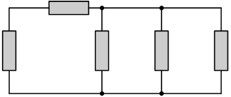
1. How many nodes does the circuit below have?
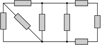
2. How many nodes does the circuit below have?
3. Identify the nodes in the circuit below.
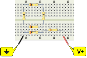
4. Identify the nodes in the circuit below.
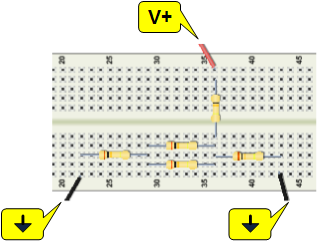
Answers
1. Three, as shown.
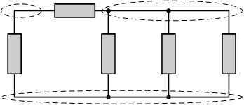
2. Five, as shown.
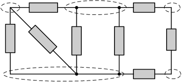
3. Five nodes, as indicated on the figure below.
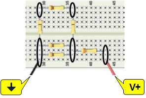
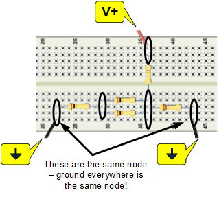
4. Four nodes, as indicated on the figure below. (Note that both ground terminals are connected internally within the Analog Discovery™. This makes them the same node.)