Table of Contents
Lab 7b: Digital Spectrum Analyzer
Download This Document
1. Objectives
- Read analog data from the Basys MX3 microphone.
- Process a block of analog data with a Discrete Fourier Transform algorithm.
- Use the Basys MX3 Character LCD to display graphical data.
2. Basic Knowledge
- How to display text on a character LCD
3. Equipment List
3.1. Hardware
- Workstation computer running Windows 10 or higher, MAC OS, or Linux
In addition, we suggest the following instruments:
3.2. Software
The following programs must be installed on your development work station:
- WaveForms (if using the Analog Discovery 2)
4. Project Takeaways
- How to implement a fast Fourier transform in C using a PIC32MX microprocessor.
- How to use the PIC32 processor to analyze a signal in real time.
- How to display the spectral energy of a real-time signal.
- How to generate a graphical display on a character LCD.
5. Fundamental Concepts
This unit focuses on processing signals in the audio frequency range using digital signal processing (DSP) concepts with the PIC32MX370 microprocessor. This lab uses Discrete Fourier Transforms (DFT) to detect the presence of signals within specified frequency bands. The purpose is to teach how to implement fast Fourier transforms using the MIPS DSP library function for the PIC32MX microprocessor in lieu of specialized digital signal processors.
5.1. Feedback Control
The Fourier Transform is an essential mathematical tool for studying many natural phenomena and engineering problems. The Fourier Transform is used to decompose time domain signals, such as the one expressed by Eq. 5.1, into a combination of sine waves of varying amplitude and phase, as expressed by Eq. 5.2. Note that while Eq. 5.1 expresses $x$ as a function of time, Eq. 5.2 expresses $x$ as a function of frequency, $f$. Since both $x(t)$ and $X(f)$ are continuous in nature, they represent expressions that cannot be operated on by a digital computer. Hence $x(t)$ must first be sampled using an analog-to-digital converter (ADC) that has a constant sampling period, $Ts$. The sampling frequency, $Fs$, is the inverse of the sampling period $Ts$. This allows the approximation of Eq. 5.2, using a Discrete Fourier Transform (DFT) algorithm.
$$x(t) = A_m \sin (2\pi f_0 t + \varphi) \qquad (\text{Eq. 5.1})$$
$$X(f) = \int_{t=-\infty}^\infty x(t) \cdot e^{-j 2 \pi t f_0} df \qquad (\text{Eq. 5.2})$$
5.2. Discrete Fourier Transform
When the continuous time domain signal of Eq. 5.1 is sampled, we get a series of discrete data values as a function of the sample number, as shown in Eq. 5.3. Eq. 5.4 is the expression for converting the series of sampled inputs into a set of complex values representing the phase and magnitude of the original signal at discrete frequencies. Since $x(n)$ represents samples of a continuous signal at discrete points in time, $X_k$ represents the same signal as discrete frequencies, hence the Discrete Fourier Transform or DFT.
There is a one to one correlation of the range of $n$ to the range of $k$. This means that processing $N$ samples of data will result in the magnitude and phase of $N$ discrete frequency components, starting with the sampling frequency, zero and continuing to $Fs/2$ in steps of $Fs/N$.
$$x(n) = A_m \sin (2 \pi fnT + \varphi) \qquad (\text{Eq. 5.3})$$
$$X_k = \sum_{n=0}^{N-1} x_n e^{-j 2\pi k \frac{n}{N}} = \sum_{n=0}^{N-1} x_n \cdot \bigg[ \cos \bigg( \frac{2\pi kn}{N} \bigg) - j \sin \bigg( \frac{2\pi k n }{N} \bigg) \bigg] \qquad (\text{Eq. 5.4})$$
While Eq. 5.4 is the analysis equation, Eq. 5.5 is the synthesis equation. Note that the only differences between Eq. 5.4 and Eq. 5.5 are the (1/N) multiplier and the sign of the complex exponent of $e$. A complex signal can be represented in the form of the summation of a selected set of complex pairs, or magnitude-phase pairs, that can be used to reconstruct a very large original time domain signal, thus constituting a form of data compression.
$$x_n = \frac{1}{N} \sum_{k=0}^{N-1} X_k e^{j2 \pi k \frac{n}{N}} \qquad (\text{Eq. 5.5})$$
Listing A.1 of Appendix A is the C code for implementing the algorithm of Eq. 5.4 in the form of a non-recursive, or finite impulse response filter (FIR). FIR filters are discussed in some detail in the Unit 7 text. Although the code is straightforward, the algorithm applied to any large size data set will require extensive computer execution time to complete the computations. The computational complexity, (based upon the number of multiply and accumulate or MAC operations) is frequently expressed as the order of N squared, or $O(N^2)$, where $N$ is the size of the DFT. Measurements show that 16.690 ms is required to compute a 32 point DFT when running on the PIC32MX370 processor at 80 MHz. This leads us to the conclusion that it would require four times as long to compute a DFT twice the size. One can easily see that DFT processing of large data sets can overwhelm a microcontroller with limited capability.
5.3. Fast Fourier Transform C Code
A fast Fourier transform (FFT) is a discrete Fourier transform algorithm which reduces the number of computations needed for a size $N$ DFT from $2N^2$ to $2log(N)_2$. The caveat is that N must be a power of 2. Although the theory behind the FFT algorithm is beyond the scope of this tutorial, its application to creating a spectrum analyzer is not. Using an FFT algorithm reduces the number of MAC instructions from 4096 to 320. Listing A.2 through A.4 are the functions to implement the Cooley-Tukey FFT algorithm using conventional C statements. The execution time for a 32 point FFT using this algorithm is reduced to 252 μs, which is 66 times faster than the execution speed for the DFT algorithm shown in Listing A.1. (Wow!)
As the famous infomercials shout, “Wait! That’s not all!” Using the MIPS DSP library mips_ff16 function we can reduce the execution time to 26 μs. This is almost 10 times faster than the C code in Listings A.2 through A.4 and is 642 times faster than Listing A.1! Is the MIPS DSP library using magic? Not quite. The MIPS DSP library function shown in Listing A.6 is optimized in assembler language. That’s why it is called a fast Fourier transform.
Listing A.5 declares the coefficient array in the statement, #define fftc fft16c32, which declares an array of 32 16-bit signed constants that are pre-defined FFT coefficients. In Listing A.6, the line of code mips_fft16( FOut, TIn, (int16c *)fftc, Scratch, LOG2FFTLEN); shows there are pointers to four arrays and an integer is passed as arguments. Fout, the result array, and Tin, the input data, are 2 by N 16-bit integer arrays for the real and imaginary parts of the variable. Although Tin is a complex variable array, the imaginary part is set to zero for real data sets. The array (int16c *)fftc is defined above. The Scratch array is used for temporary results that do not need to be remembered from one function call to the next. Finally, the integer, LOG2FFTLEN, is the log base 2 of the number of points in the FFT.
Since all of the DFT algorithms described in Listing A.1 through return arrays that contain complex values, they must be converted to real values to be usable for graphical LCD display. Listing 6.7 provides the source code for converting a pair of complex integer values to a real integer. Tests have shown that the execution time of integer conversion is three time faster than using a floating point square root function. See Reference 6 for additional details regarding this algorithm.
The DFT results cover the span of zero to $2\pi$, corresponding to zero to the sampling frequency, Fs. Each output represents the signal frequency in steps of $Fs/N (\Delta N)$ where N is the number of samples being processed. The DFT output is only valid for the first $n = 0$ to $N/2 – 1$ frequencies, or from zero to $(Fs/2 – \Delta N)$. The outputs for the $n = N/2$ to $N-1$ frequencies are complex conjugates of the first and can be ignored for our purposes.
6. Problem Statement
The objective for this lab is to create a graphical spectrum analyzer as modeled in Fig. 8.1. Figure 8.2 shows the LCD and 7-segment display for the result outputs. Figure 8.3 through 8.5 provide an approach to the software organization for this lab. Figure 8.4 shows the tasks to be completed for the system initialization.
7. Background Information
Since DFT algorithms are essentially FIR digital filters, refer to Unit 7 section 6.3.1 for background information.
8. Lab 7b
8.1. Requirements
- Set Time 2 to sample the microphone input at the rate of 16 kHz.
- Implement a double buffer for the sampled analog data such that the FFT is processing one buffer while the other is being filled.
- Compute the 16 FFT outputs using the code provided in Appendix A Listings A.5 through A.7.
- Using custom LCD characters, display the energy at the 15 frequencies corresponding to zero to 7500 Hz with 500 Hz intervals. (See Reference 7 and 8.)
- Display the maximum FFT frequency on the 7-segment display provided the detected energy level is above a minimum set point.
- Update the display every 50ms.
- Adjust the MIC Volume control for maxim display for a reasonable volume tone. (Suggestion: Program a second Basys MX3 with the code from Lab 6a to generate single frequency test inputs.)
 Figure 8.1. Block diagram of a digital spectrum analyzer.
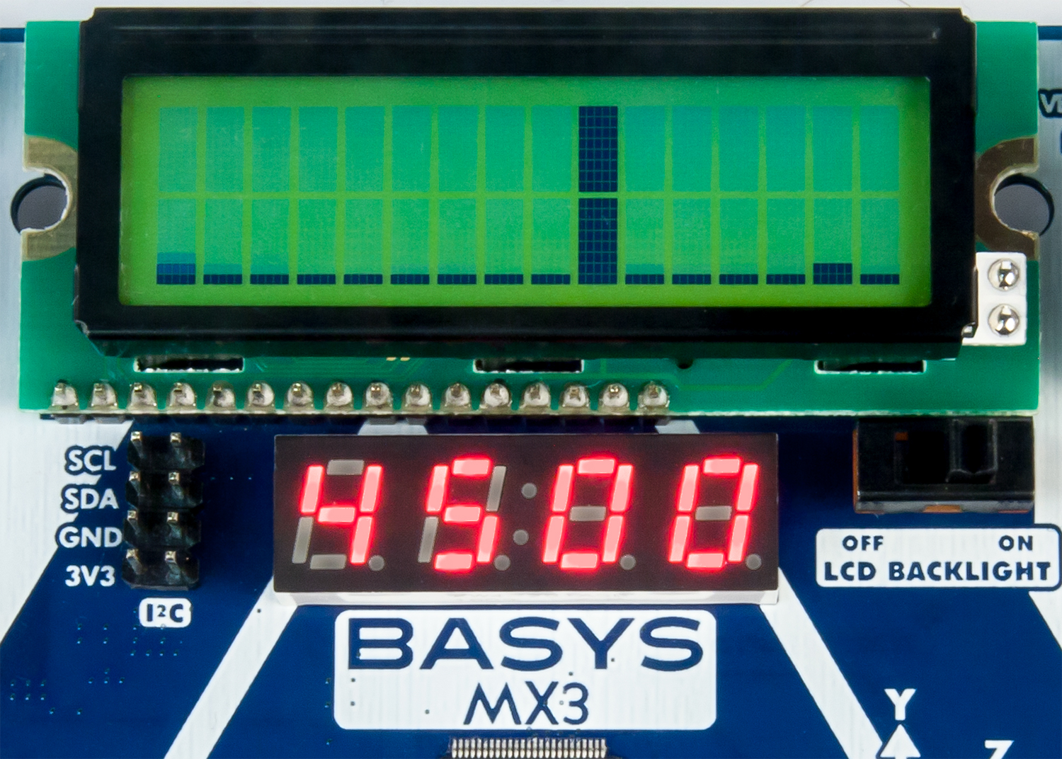 Figure 8.2. LCD and 7-segment display for spectrum analyzer.
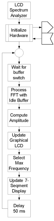 Figure 8.3. Control flow diagram for LCD spectrum analyzer.
 Figure 8.4. Control flow diagram for LCD spectrum analyzer initialization.
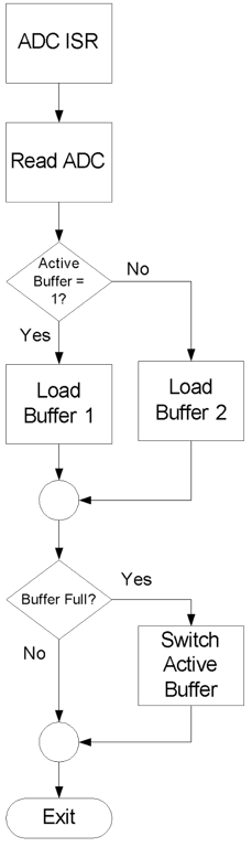 Figure 8.5. ADC complete ISR.
8.2. Design, Construction, Testing
In previous labs, steps were laid out to lead the student through effective design, construction and testing procedures. This is now left up to the student to complete on their own, ensuring the design requirements listed in section 8.1 are met.
9. Questions
- Theoretically, how much time is required to fill one data buffer?
- Theoretically, what is the maximum rate that the LCD and 7-Segment display can be updated?
- In reality, what is the maximum rate that the LCD and 7-Segment display can be updated?
- Why would one want to update the displays at a rate slower than the theoretical maximum speed?
- How many times will a buffer be filled during the time needed to display the results for computing the FFT of one block of data? What are the potential problems here?
- How can your answer to question 5 be resolved?
10. References
- Basys MX3 Trainer Board Reference Manual.
- PIC32 Family Reference Manual, Timers Section 14: http://ww1.microchip.com/downloads/en/DeviceDoc/61105E.pdf.
- Steven W. Smith, The Scientist and Engineer’s Guide to Digital Signal Processing, http://www.dspguide.com/pdfbook.htm.
- Cooley-Tukey FFT for 16-bit Integer Numbers, Microchip Technology, http://www.embeddedcodesource.com/codesnippet/cooley-tukey-fft-for-16-bit-integer-numbers.
- Calculate an integer square root, http://www.codecodex.com/wiki/Calculate_an_integer_square_root.
- Printing Custom Characters on a Character LCD, http://deanandara.com/robots/ApuLcd.html.
- Getting Graphic; Defining Custom LCD Characters, https://www.seetron.com/archive/pdf/lcd_an2.pdf.
Appendix A: Discrete Fourier Transform Software
Listing A.1. Code to Implement a DFT Based on Eq. 5.4
#define FFT_SIZE	###  	// Any integer value
void DFT(int16_t *x, int16_t *y_re, int16_t *y_im)
{
int k,n;
float w = PIx2/FFT_SIZE;

   for(k=0; k<FFT_SIZE; k++)
   {
       y_re[k] = 0;
       y_im[k] = 0;
       for(n=0; n < SIZE; n++)
       {
           y_re[k] += x[n] * cos(w * n * k);
           y_im[k] += x[n] * sin(w * n * k);
       }
   }

}
Listing A.2. Constant Declarations for Block Processing C for FFT Algorithm
#define FFT_SIZE	###  	// An integer of size equal to a power of 2
const int16_t bitPermutationTable[FFT_SIZE] =
{0,16,8,24,4,20,12,28,2,18,10,26,6,22,1
4,30,1,17,9,25,5,21,13,29,3,19,11,27,7,
23,15,31};
Listing A.3. Block Processing C for FFT Algorithm
void FFT(int16_t* bufferRe, int16_t* bufferIm)
{
   int16_t bl;                 // current butterfly size
   int16_t p;                  // half current butterfly size
   int16_t k;                  // current level number
   int16_t m;                  // coefficient counter
   int16_t i;   // first point offset
   int16_t j;   // second point offset
   int16_t wRe; // current twiddle coefficient (real)
   int16_t wIm; // current twiddle coefficient (imaginary)
   int16_t temp;

   bl = FFT_SIZE;             	// current butterfly size
   p  = FFT_SIZE >> 1;          // current butterfly size divided by 2
   k  = 0;                      // level number

   while (p > 0)
   {
	for (m=0; m<p; m++)
	{
	    j = m << k; // coefficient offset
           wRe =  twiddleCoefficients[(j + FFT_SIZE / 4)];
	    wIm = -twiddleCoefficients[j];

	    for (i=m; i<FFT_SIZE; I += bl)         // cycle for all butterflies here
	    {
	        j = i + p;                         // i - offset for the first point
          // j - offset for the second point
        FFT2(bufferRe+i, bufferIm+i, bufferRe+j, bufferIm+j, wRe, wIm);
	    }
	}

	k++;
	p >>= 1;
       bl >>= 1;
   }

   for(i=1; i<(FFT_SIZE - 1); i++) // Put results into regular order
   {
       j = bitPermutationTable[i];

       if(j <= i)
       {
           continue;
       }

       temp = bufferRe[i];
       bufferRe[i] = bufferRe[j];
       bufferRe[j] = temp;

       temp = bufferIm[i];
       bufferIm[i] = bufferIm[j];
       bufferIm[j] = temp;
   }
}
Listing A.4. Butterfly Computation for Block Processing for FFT Algorithm
void FFT2(int16_t *ReA, int16_t *ImA, int16_t *ReB, int16_t *ImB,
         int16_t Wr, int16_t Wi)
{
int w0, w1, w2, w3, w6;

// Scale for Q1.15
   w0 = *ReA >> 1;
   w1 = *ImA >> 1;
   w2 = *ReB >> 1;
   w3 = *ImB >> 1;

// ;;;;;;;;;;;;;;;;;;;;;;;;;;;;;;;;;;;;;;;;;;;;;;;;;;;;;;;;;;;;;;;
//  PLUS PATH
// ;;;;;;;;;;;;;;;;;;;;;;;;;;;;;;;;;;;;;;;;;;;;;;;;;;;;;;;;;;;;;;;
//  SAVE REAL RESULT
//    w6 = w0 + w2;
   *ReA = (int16_t) (w0 + w2);

//  SAVE IMAGINARY RESULT
//    w7 = w1 + w3;
   *ImA = (int16_t) (w1 + w3);

//;;;;;;;;;;;;;;;;;;;;;;;;;;;;;;;;;;;;;;;;;;;;;;;;;;;;;;;;;;;;;;;
//    MINUS PATH
//;;;;;;;;;;;;;;;;;;;;;;;;;;;;;;;;;;;;;;;;;;;;;;;;;;;;;;;;;;;;;;;

   w0 = w0 - w2;
   w1 = w1 - w3;

//  multiply by coefficient
   w2 = w0 * Wr;
   w6 = w1 * Wi;
   w2 = (w2 - w6) >> 15;

//  SAVE RESULT W3 HERE (REAL)
//    w2 = w2 >> 15;
   *ReB = (int16_t) w2 ;

//  multiply by coefficient
   w2 = w0 * Wi;
   w6 = w1 * Wr;
   w2 = (w2 + w6) >> 15;

//  SAVE RESULT W3 HERE (IMAGINARY)
   *ImB = (int16_t) w2;
}
Listing A.5. Global Declarations for MIPS DSP Library FFT Algorithm
#include <stdint.h> 			// Standard integer definitions
#include <dsplib_dsp.h>			// MIPs DSP library
#include <fftc.h>

// Define FFT coefficients pre calculated in DSP lib
#define fftc            fft16c32        // Defined in fftc.h, for N = 32

#define LOG2FFTLEN      5			// Log base 2 of FFT length
#define FFTLEN          32			// 32 point FFT
Listing A.6. MIPS DSP Library FFT Algorithm
void FFT(int16c *FOut, int16c *TIn)
{
int16c Scratch[FFTLEN];			// Scratch pad memory
   mips_fft16( FOut, TIn, (int16c *)fftc, Scratch, LOG2FFTLEN);
}
Listing A.7. Absolute Value of a Complex Variable
/*************************************************************************
A = SQRT(Re^2 + Im^2)
http://www.codecodex.com/wiki/Calculate_an_integer_square_root#C
*************************************************************************/
uint16_t FFTAmplitude(int16_t re, int16_t im)
{
uint32_t _bit = ((uint32_t)1) << 30;
uint32_t num;
uint32_t res = 0;

   num = ((uint32_t)re)*re + ((uint32_t)im)*im;

// 32 bit integer square root calculation.
   while (_bit > num)
       _bit >>= 2;

   while (_bit != 0)
   {
       if (num >= res + _bit)
       {
           num -= res + _bit;
           res = (res >> 1) + _bit;
       }
       else
           res >>= 1;
       _bit >>= 2;
   }
   return ((uint16_t)res);
}
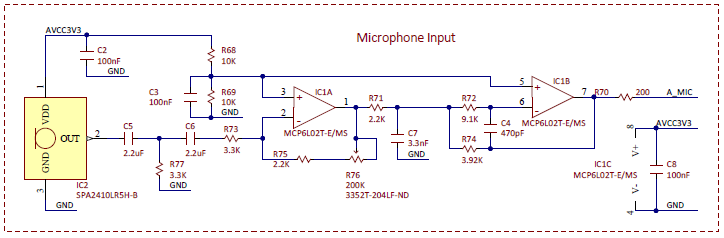 Figure B.1. Basys MX3 Microphone Schematic.