Table of Contents
Lab 2a: Dynamic Real-time Systems
Download This Document
1. Objectives
- Develop an application of foreground-background task scheduling.
- Use change notification interrupts to detect push button presses and releases.
- Eliminate multiple button operations using a timer interrupt to implement a non-blocking delay.
- Implement the push-on / push off operation using a software-based finite state machine.
2. Basic Knowledge
3. Equipment List
3.1. Hardware
- Workstation computer running Windows 10 or higher, MAC OS, or Linux
In addition, we suggest the following instruments:
3.2. Software:
4. Project Takeaways
- How to set the period of a PIC32 Timer.
- How to write a software state machine.
- How to allocate tasks to either foreground or background scheduling.
5. Fundamental Concepts
Microprocessor-based systems that we use today, such as coffee makers and microwave ovens, require a human-machine interface (HMI). HMI inputs are implemented with some type of electromechanical device such as touch pads, push buttons, toggles, and rotary switches. Such devices rarely produce clean (noise free) logical signals to the inputs of high speed digital electronics. Special software and/or hardware is required to reduce or entirely eliminate the noise from these signals.
6. Problem Statement
The design challenge titled “Push-on/Push-off Buttons” presented on the Digilent Learn website targets the chipKIT Pro circuit board. This lab modifies the requirements to include non-blocking button press and release detection using change notification interrupts. The requirements are:
Write the code that converts the three momentary contact pushbuttons to operate as push-on/push-off buttons and that satisfies the following specifications:
- The state of the three push buttons BTNR, BTNC, and BTND are displayed on LED0 through LED2.
- The function provides for a 20 ms debounce period for every press and release of a push button.
- The new button state is reported at the start of the 20 ms debounce period.
- The button polling function is to be non-blocking during the 20 ms debounce period.
7. Background Information
Digital logic can be classified as combinational or sequential. Combinational circuits are logic circuits whose outputs respond immediately to the current inputs, as was presented in Lab 1a. No memory circuits are required for combinational logic circuits. In a sequential logic circuit, the outputs depend on the current inputs plus state, requiring some form of memory. In hardware, memory is provided by flip-flops, latches, and counters. Principle of Equivalence of Hardware and Software: Anything that can be done with software can also be done with hardware, and anything that can be done with hardware can also be done with software. The exception to this principle is speed of implementation. Hardware has considerably faster time response. This is true of discrete logical electronic devices but even more so with modern FPGAs.
Momentary contact switches have one stable state, that being when the switch is in the relaxed condition. A push-on/push-off switch is a type of a mechanical toggle switch that has two stable states. The common approach to implementing a push-on/push-off operation with a momentary contact push button is to provide some type of memory which is usually electronic in nature, such as a flip-flop or latch. Section 7.6 of Unit 2 presents a state machine implementation of the push-on/push-off toggle switch. Since we want to detect the push button operations using change notification interrupts that detect both openings and closings, the state machine presented in Unit 2 has four stable states.
Electromechanical devices, such as switches and relays that are commonly used for microprocessor inputs, are mass-spring devices that will result in contact bounce when opening and closing. Combinational logic circuits will see the multiple contact closures and openings as multiple events unless signal conditioning circuits are used. Usually some type of delay after the initial contact operation is implemented so subsequent operations are ignored for a period of time. The delay can be implemented using an analog low-pass circuit with a resistor and capacitor in addition to electronic devices. Such circuits are costly in terms of circuit board real-estate. As an alternative, there are specialty electronic circuits as well as FPGA designs that can be used to remove contact bounce.
High speed modern microprocessors are also subject to contact bounce issues. Contact bounce issues can be mitigated using simple time delays, such as the polling software delay used in Lab 1b; however, this delay implementation is a blocking procedure that inhibits the processor from executing code for another task during the delay period. Delays implemented with interrupts are used to notify the processor to execute code for another application task and to notify again when the delay period has expired. This implementation of a delay is non-blocking.
8. Lab 2a
8.1. Requirements
- BTNR is to toggle LED0.
- BTNC is to toggle LED1.
- BTND is to toggle LED2.
- All LED changes are to occur immediately following a push button press.
- A 20 ms debounce delay inhibits the CN only for the button pressed or released.
- The push-on / push-off operation must allow multiple simultaneous push button operations.
- A single conditional statement in the infinite loop is to call a single state machine function that implements the push-on / push-off operations for all three push buttons.
8.2. Design Phase
- Concept maps.
- Data Flow diagram.
- Control Flow diagram.
- Schematic diagrams.
- The schematic diagrams of the connections with the PIC32 processor are shown in Appendix A.
8.3. Construction Phase
- Write a problem statement that lists the requirements.
- Determine what elements of the Basys MX3 board will be used.
- List the processor hardware resources that you will be using in this design.
- Generate a data flow diagram that identifies tasks (functions) and the information that needs to be passed between these tasks.
- Sketch a control flow diagram for this program that identifies what is to be done in the initialization section and what will be done in the infinite loop.
- Write a test plan that you will use to validate your software design.
- Create a new project for the Basys MX3 trainer board. Name this project Lab2a.
- Copy the “config_bits.h” file to the project folder
- Add the “config_bits.h” file to the project list of Header Files.
- Create a new “mainfile” to the project. Name this file “main.c”.
- Add “config_bits.h” to the top of main.c.
- Create a function called main by writing “int main(void) { … }”.
- Within the initialization section of the main function:
- Set the PORT A TRIS register to set the bits for LED0, LED1, and LED1 as digital outputs.
- Set the PORT A TRIS register to set the IO pin for BTND as a digital input.
- Set the PORT B TRIS register to set the IO pin for BTNR as a digital input.
- Set the PORT F TRIS register to set the IO pin for BTNC as a digital input.
- Write a shell program that passes the data identified in step 4 above.
- 8. Develop the task code one task at a time. Verify each task as it is developed.
8.4. Testing
- Verify that each push button individually operates as push-on/push-off in all combinations of LED0 through LED2 on and off.
- Verify that each push button individually operates as push-on/push-off when another push button is held depressed.
- Initialize RE0 as an output. Set the Analog Discovery 2 for Logic Display and add signal DIO 0.
- Using LATEbits.LATE0 = 1; and LATEbits.LATE0 = 0;, determine the execution time of the Timer 1 ISR.
- Using LATEbits.LATE0 = 1; and LATEbits.LATE0 = 0;, determine the execution time of the CN ISR whenever a button is pressed.
- Using LATEbits.LATE0 = 1; and LATEbits.LATE0 = 0;, determine the execution time of the push-on / push-off state machine.
9. Questions
- How does your control flow diagram convey the fact that interrupts can occur at any time during execution of the background task?
- What is the latency from the button press until the LED changes state?
10. References
- PIC32MX330/350/370/430/450/470 Family Data Sheet
- Basys MX3 Reference Manual
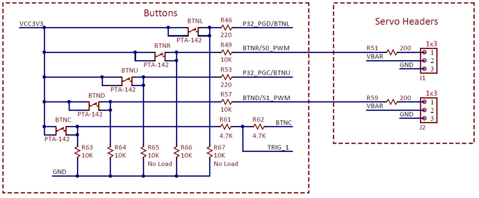 Figure A.1. Push button schematic diagram.
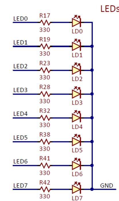 Figure A.2. Basys MX3 schematic diagram for LED0 through LED8.